In precision manufacturing, quality control isn’t just another box to check on the shop floor—it’s the only thing standing between a flawless production run and a brutal product recall. For decades, QA teams relied on manual calipers, micrometers, height gauges, and traditional Coordinate Measuring Machines (CMMs). While those tools served their purpose, manual checks capture only isolated touch points across a physical component. If a cast casing warps along a subtle curve or a machined bracket shifts slightly out of alignment between check sites, traditional tools miss the defect entirely.
Catching structural variations early takes total dimensional visibility. High-precision 3D dimensional inspection workflows give quality control engineers complete surface coverage down to the micron. Sourcing professional 3D scanning for quality inspection lets local manufacturers, machine shops, and tooling facilities verify part geometry, spot hidden production flaws, and streamline batch approvals before defective components reach assembly lines or ship to clients.
The Hidden Risks of Traditional Quality Control
Conventional metrology methods hit clear walls in fast-paced production settings. Mechanical probes and hand gauges take forever to set up, require deep operator expertise, and leave massive blind spots across intricate geometric features:
- Sparse Measurement Density: Calipers and traditional CMM probes measure specific discrete points, leaving uninspected surfaces where warpage or shrinkage easily goes unnoticed.
- Touch-Probe Distortion: Tactile CMM needles can flex or compress soft materials, rubber gaskets, and thin-walled plastic parts during physical contact, throwing off your measurement readings.
- Severe Production Bottlenecks: Manual checking creates huge QA queues on shop floors, forcing production managers to choose between slowing throughput or skipping thorough component inspections.
Adopting 3D scanning for quality inspection fixes these quality control bottlenecks by capturing millions of spatial data points across complex surfaces in seconds. According to a study, integrating automated 3D optical metrology and digital spatial inspection into quality assurance workflows cuts part inspection cycle times while reducing scrap and rework costs across industrial facilities.
Where 3D Optical Inspection Delivers the Highest ROI
High-definition optical metrology isn’t just about verifying basic length and width—it acts as a core decision engine across the entire manufacturing lifecycle. Integrating 3D scanning for quality inspection yields clear practical benefits across several critical production phases:
- First Article Inspection (FAI): Verifying the first off-tool parts from a new injection mold or CNC production run against original CAD designs to approve tooling before full-scale manufacturing begins.
- Color Map Deviation Analysis: Generating visual 3D color heat maps that immediately highlight dimensional shifts, surface warpage, wall thinning, or tool wear across whole components.
- Geometric Dimensioning & Tolerancing (GD&T): Verifying complex geometric tolerances—such as flatness, concentricity, parallelism, and true position—without writing tedious CMM probe paths.
- In-Line Quality Auditing: Periodically scanning parts straight off assembly lines to detect gradual mold wear or tool drift before out-of-tolerance components contaminate entire production runs.
Specialized 3D scanning for quality inspection keeps quality control managers in full control of shop-floor precision without burning hours on manual spot checks.
How 3D Metrology Works: From Physical Part to Heat Map Report
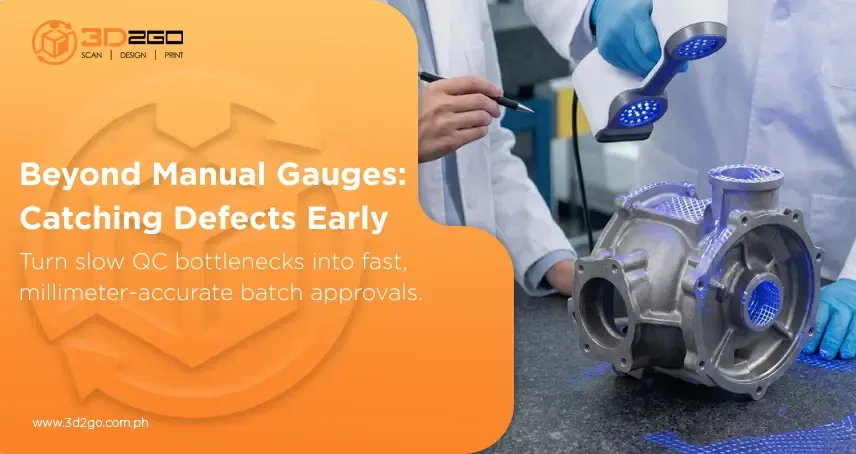
3D optical inspection utilizes high-speed structured light or handheld laser scanners to sweep physical components, recording dense coordinate data across every curve, hole, and edge.
When you send components out for 3D scanning for quality inspection, your parts move through a clear, systematic metrology pipeline:
- Part Preparation & Optical Setup: Technicians position the component on a stabilized scanning table or turntable, applying high-accuracy reference targets and non-reflective anti-glare sprays for glossy or dark metal surfaces.
- High-Resolution Surface Capture: Industrial 3D scanners emit fine blue light patterns or laser grids across the part, capturing millions of precise XYZ coordinate points within seconds.
- Point Cloud Alignment & Mesh Generation: Specialized metrology software cleans, stitches, and converts raw point cloud data into a watertight 3D polygonal mesh representing the exact physical component.
- CAD Alignment & Inspection Comparison: The generated 3D mesh is digitally aligned directly over the original nominal CAD file using best-fit or datum alignment protocols.
- Color Deviation Mapping & Report Generation: The software instantly calculates structural variances and produces clear color heat maps, GD&T callouts, and PDF inspection pass/fail certificates.
Relying on a disciplined 3D scanning for quality inspection workflow ensures your engineering team receives clear, actionable inspection reports ready for immediate audit review.
Optical 3D Scanning vs. Traditional Metrology Tools
Comparing 3D optical surface capture against legacy inspection methods highlights clear operational advantages for modern machine shops and fabrication facilities:
| Inspection Feature | Traditional CMM & Manual Gauges | Optical 3D Scanning |
| Data Coverage | Sparse, point-by-point contact | Full-field surface capture (Millions of points) |
| Inspection Speed | Hours or days for complex geometry | Minutes per component |
| Surface Inspection | Touch-probe contact required | Non-contact optical measurement |
| Visual Insight | Numeric tables and basic 2D drafts | 3D visual color heat maps |
| Soft/Flexible Parts | Prone to probe deformation | Completely distortion-free |
Choosing non-contact 3D scanning for quality inspection protects delicate components while providing a complete visual record of physical geometry.
Building a Digital Archive for Quality Traceability
The value of 3D inspection data extends beyond initial batch sign-offs. Every scan pass creates a permanent, high-resolution “digital twin” of the inspected component that lives in your cloud archive indefinitely.
If a client raises a quality dispute or structural failure claim months after a production run ships, quality managers can pull up the archived 3D mesh generated during 3D scanning for quality inspection. Reviewing historic inspection data provides undeniable digital proof of component dimensional accuracy at the time of manufacture, protecting your firm’s reputation and shielding your business from costly liability claims.
Eliminate Dimensional Uncertainty on Your Production Floor
Out-of-tolerance components and hidden manufacturing defects shouldn’t compromise client relationships or drain profit margins through scrap and rework. Relying on manual gauges or sparse CMM probe points leaves your production output vulnerable to undetected dimensional errors.
3D2GoPH helps manufacturers, machine shops, and engineering facilities eliminate dimensional uncertainty. As a full-service 3D technology hub in the Philippines, we manage the complete inspection pipeline under one roof—from high-resolution optical field scanning and Metrology CAD alignment to detailed 3D color deviation mapping and GD&T verification. Our team delivers accurate, actionable inspection reports tuned to your exact manufacturing standards.
Don’t let undetected tooling errors or manual survey mistakes delay your deliveries. Skip the guesswork and inspect your parts with absolute precision. Contact our team today to schedule your 3D quality inspection!